Trident Assembly Tips
The kit's packaging is designed by the assembly sequence. We strongly recommend not taking parts and pieces out of each layer. You can take every layer out but keep them as layers with parts intact.
These Assembly Tips are specific to the Trident. You will also need to refer to the General Assembly Tips that are common to the V2.4 and the Trident. The V2.4-specific assembly tips are here.
Frame

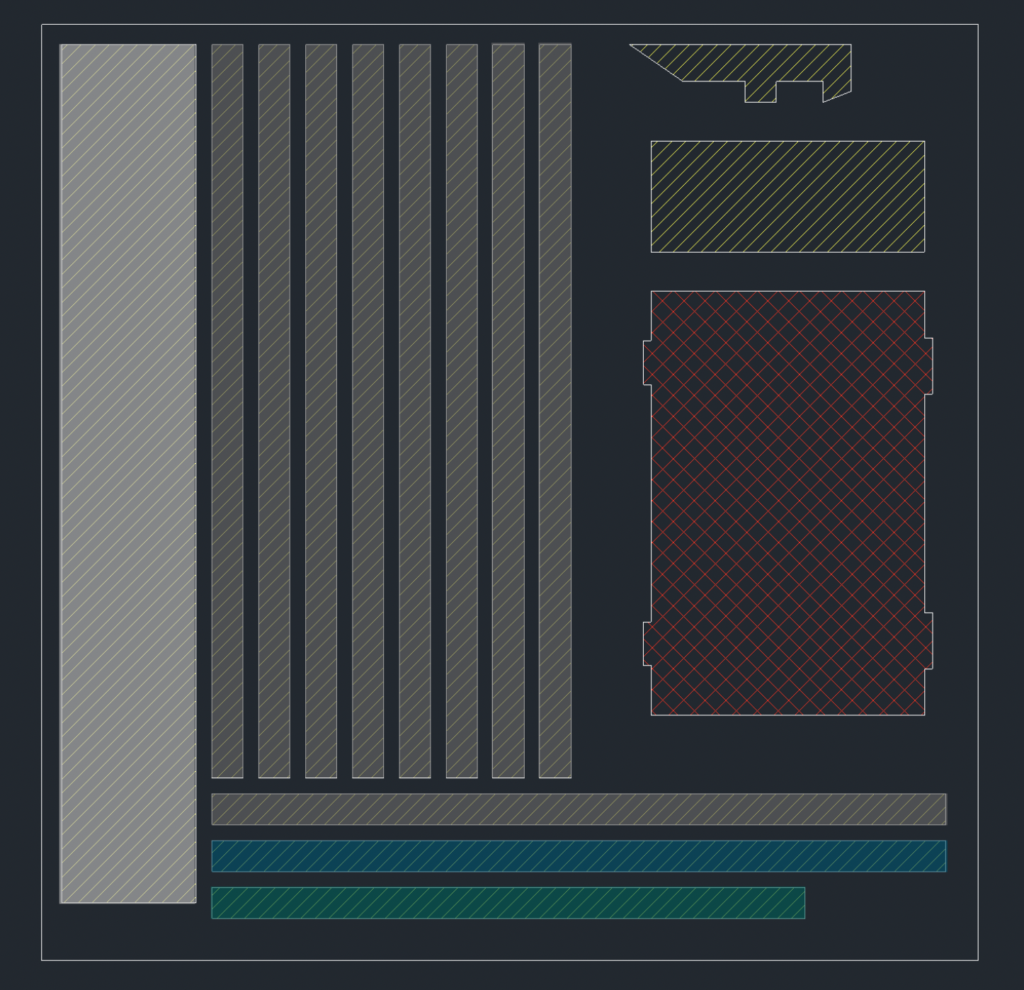
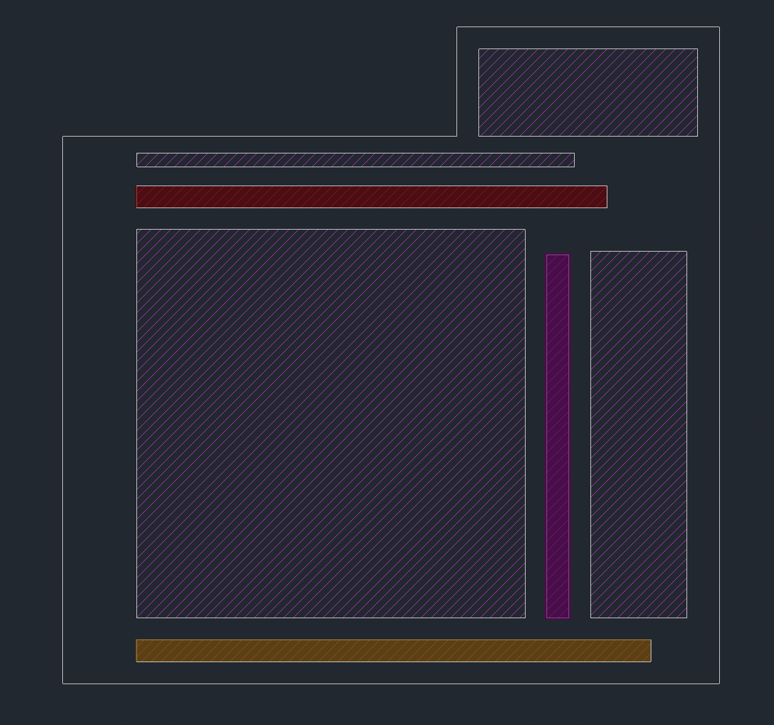
Packing Layer #1
Notice the color on the foam and the frame.
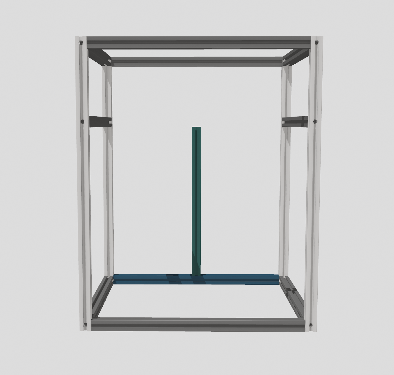
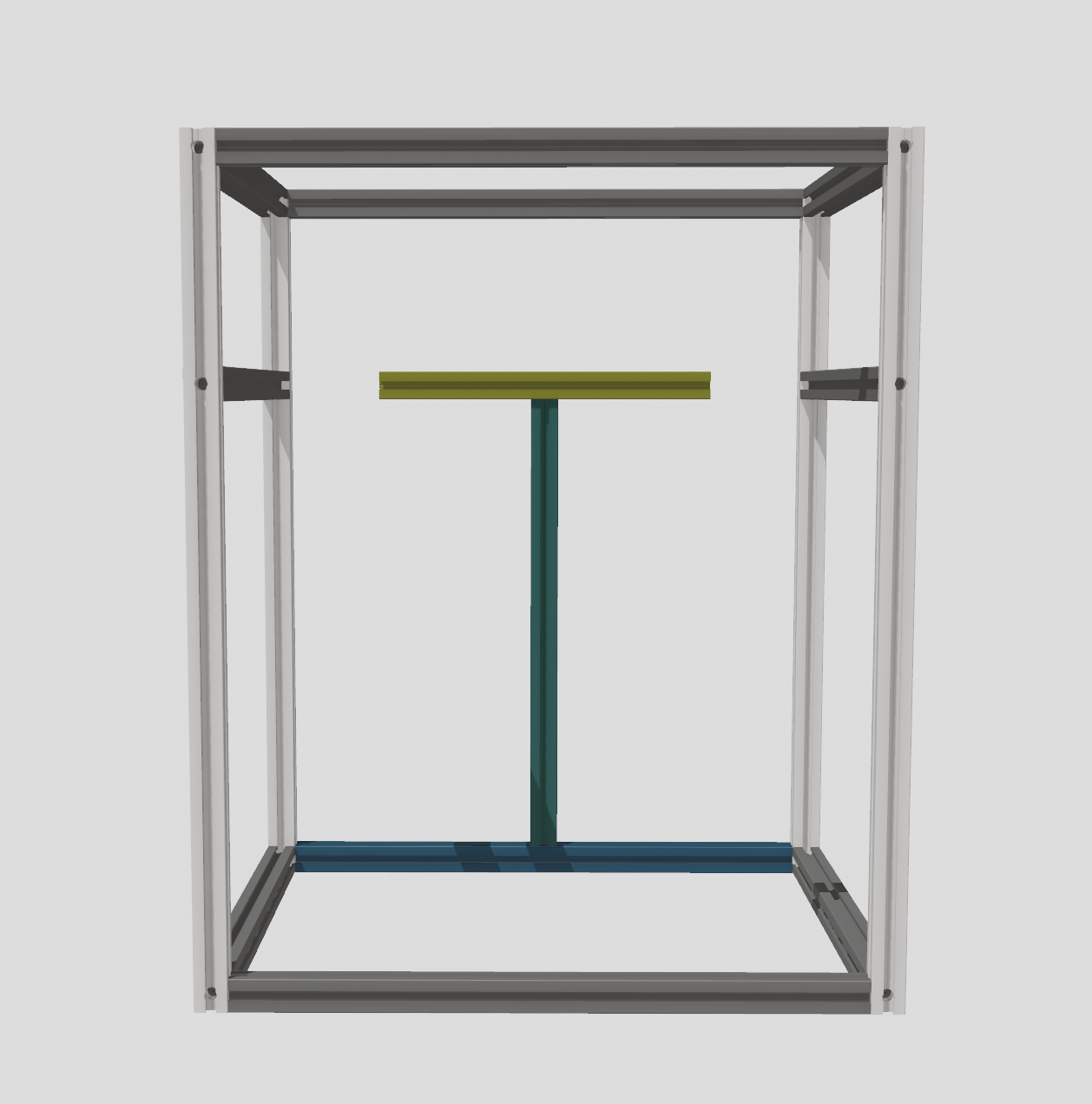
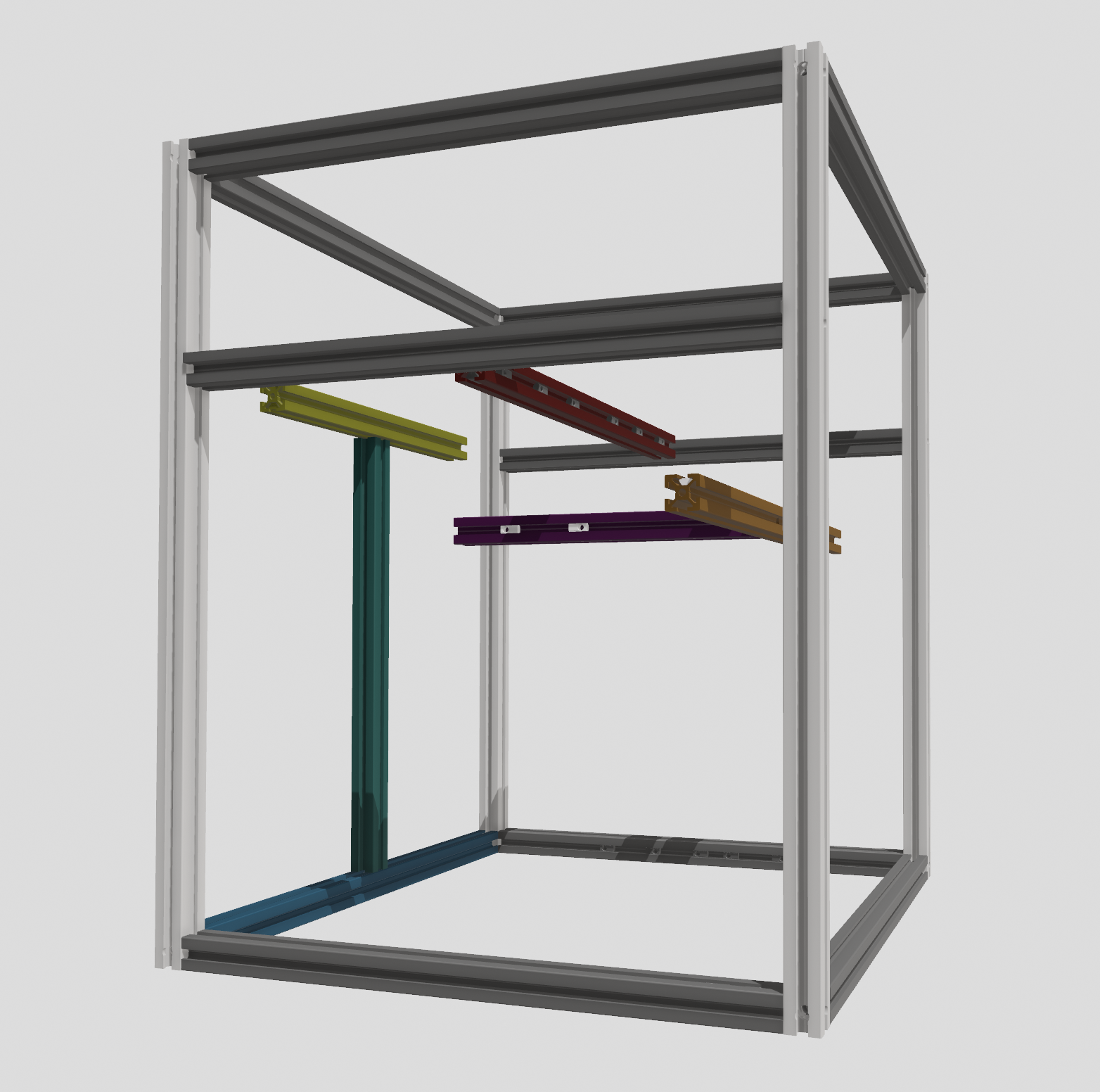
Packing Layer #2
There's only one extrusion in this layer, it's the yellow one.
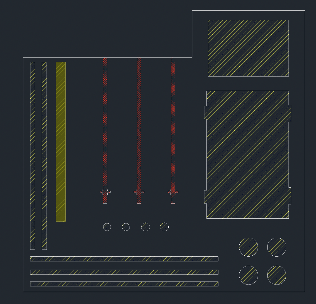
Packing Layer #3
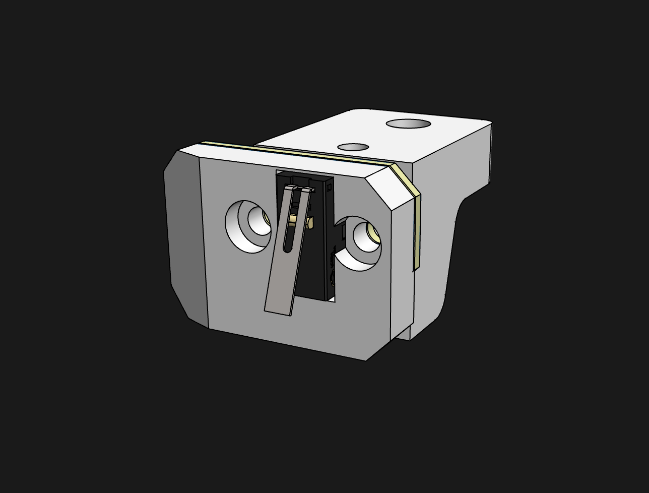
Y Endstop
1.Install two M3 inserts into these 2 holes.
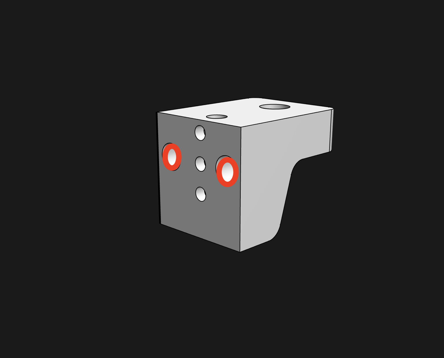
2.Use M3x8 SHCS to mount the Y endstop PCB
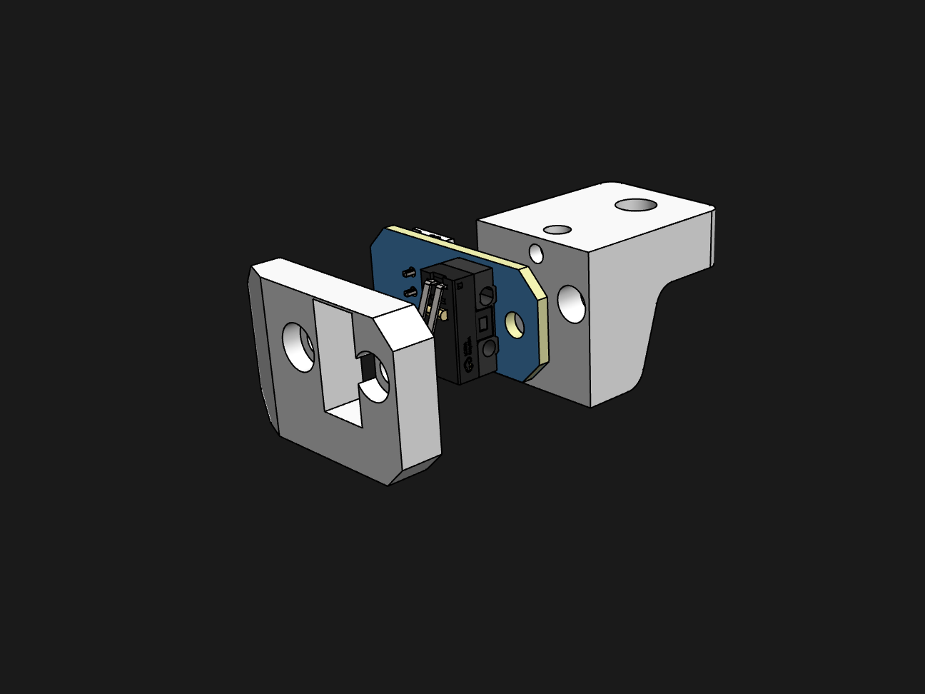
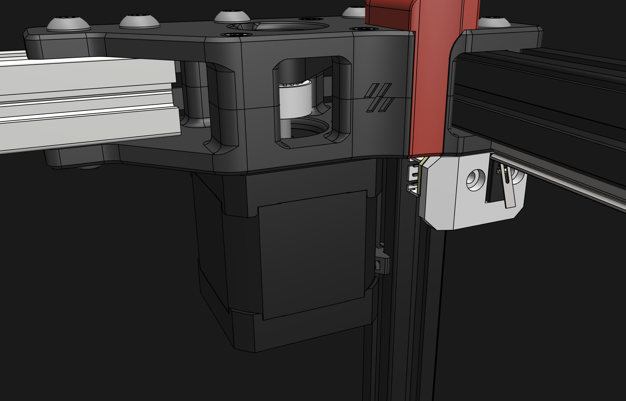
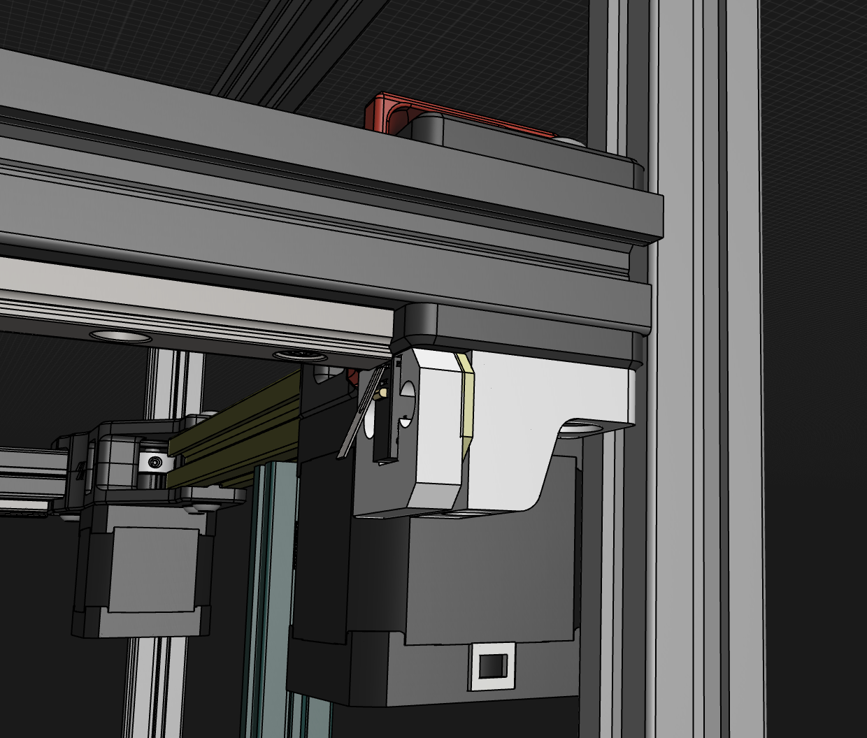
3.Install on gantry
They should install on the A drive. You need M5x16 BHCS and M3x25 SHCS here
Frame Wiring
Instead of the printed wire clip, we add more extrusion covers in the kit.
You can use them to hide the wires.
Once again, remember to refer to the General Assembly Tips for those parts of the build common between the V2.4 and the Trident (Stealthburner, Tap, etc)