Sensorless Homing Setup On M8P V2
Introduction
Sensorless homing makes use of the stallguard feature built into the TMC2209 stepper drivers plugged into the Manta M8P for the A & B motors that drive the toolhead on X & Y. Canbus and the integrated Y-endstop / chamber temperature sensor in the MPX kits requires some changes from the standard sensorless homing procedure documented in the Voron site (opens in a new tab). Nevertheless, you still want to read that page over as much of it is still applicable. This writeup will focus more on the deltas from that writeup vs. detailing the procedure in full.
Getting a basic understanding of how sensorless homing works now will be useful for setup and troubleshooting later. In short:
- The physical endstop switches are either not installed (X-endstop on Stealthburner) or not connected (Y-endstop near A motor)
- The stepper drivers plus a bit of configuration in
printer.cfgprovide a signal that is either Low in normal operation (endstop not triggered) or High (endstop triggered). - The signal from the stepper drivers gets to the Manta CPU via connection of something called the DIAG jumpers. This means three things in practice:
- First: The physical endstops must not be installed / connnected or they will interfere with the operation of sensorless homing. The DIAG jumper connection takes the place of the physical endstop connection.
- Second: The EBB SB2209 is no longer involved with homing at all. We will not install the X-endstop to the toolhead and we will completely remove the reference to this endstop in our
printer.cfg - Third: The wiring from the MPX Y-endstop / chamber thermistor will need to be modified so we can retain the chamber temperature function.
DIAG Jumper Installation
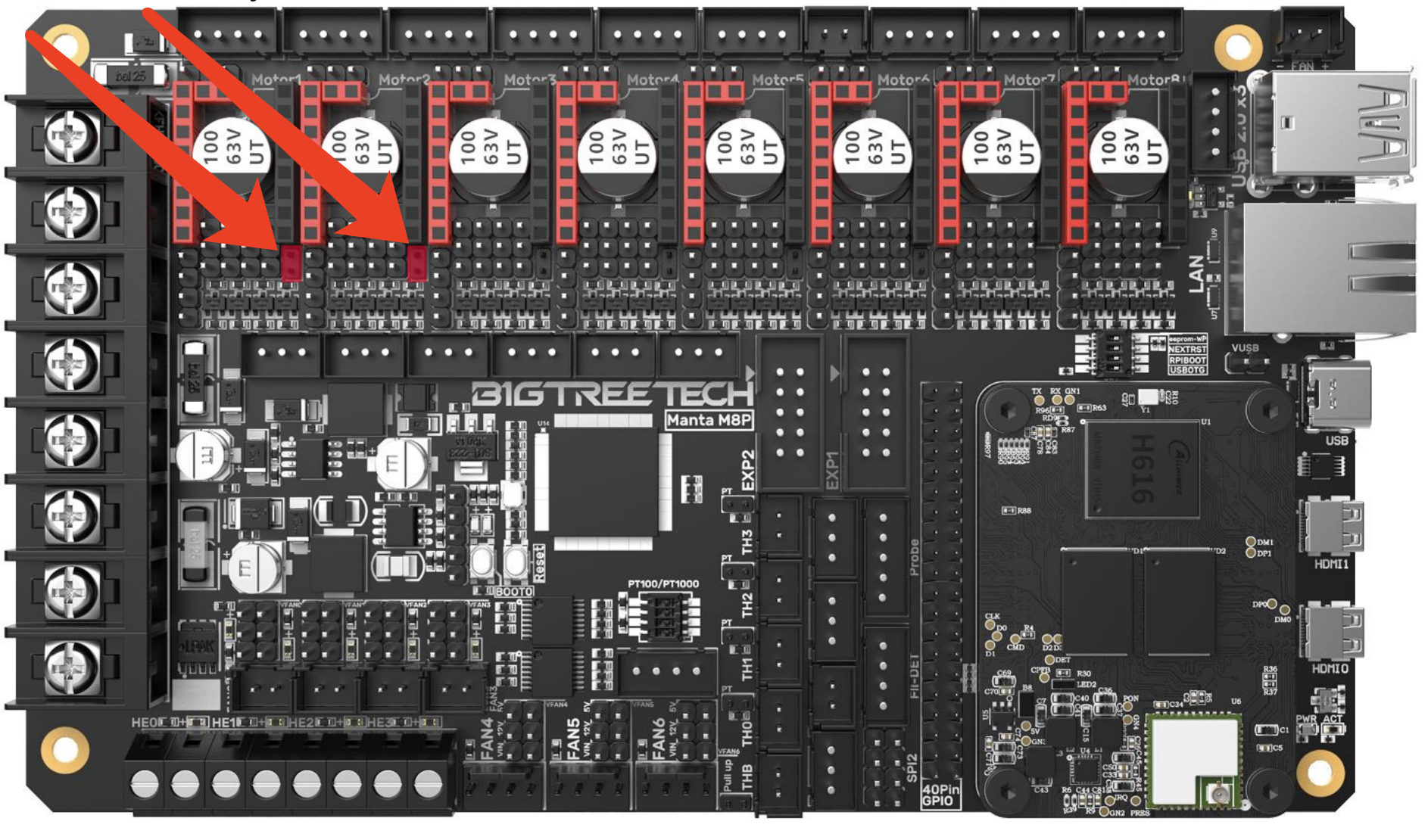
This part is straightforward. You need to install the DIAG jumper for both the A & B steppers motors as shown in this picture. These jumpers are in addition to the other jumpers that you installed when you set up the Manta for flashing.
This picture shows the Manta V1 but the DIAG jumpers are in exactly the same place for Manta V2. Note that the DIAG jumper connection requires the smaller of the two jumper sizes provided with the Manta by BTT.
Wiring
Stealthburner / EBB SB2209
The X-endstop on the Stealthburner can be removed / not installed. It probably doesn't do any harm to have it on and left connected because we will be removing all references to it in printer.cfg, but this is untested. A reason for leaving it connected might be if you wanted to switch back to physical endstops later.
Y Endstop
What MPX calls the Y Endstop PCB also includes a very small thermistor that is used for measuring the chamber temperature. We want to retain this capability so we still want to install that PCB and we still need to run the wiring to it but we need to change the wiring around a bit from the default: we want to retain a ground connection to the PCB but have the endstop switch ignored. There are two equally-effective methods for this, and the choice is up to you.
Method 1: Cable Re-pinning
This method re-pins the the chamber thermistor JST connector for the ground connection needed by the Y Endstop PCB. Refer to the picture below. The green lines illustrate the original MPX wiring. The blue lines indicate where we want to end up after re-pinning.
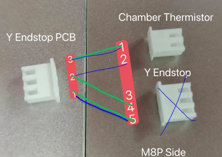
On both the three pin connectors, ground is the middle pin. The "Y Endstop PCB" has both a thermistor (across pins 2 & 3) and a switch (across pins 1 & 2). Re-pin the middle wire (“4”) from the "Y-Endstop" connector to “2” on the "Chamber Thermistor" connector. This relocates the Ground to the thermistor connection so that the M8P can read it. The wiring should now match the blue lines. The "Chamber Thermistor" will plug in to its original spot on the Manta. The "Y Endstop" connector can be left disconnected and tucked away in the PVC wiring channel in case you want to revert back to physical endstops later.
Method 2: Unused Endstop Connection
Method 2 is simple: leave the connector pinouts as-is and plug the 3-pin "Y Endstop" connector into another unused endstop connector on the Manta board. That retains the ground connection to the Y Endstop PCB without otherwise interrupting motor operation.
Initial Software Configuration
Changes to printer.cfg
Before you run through the Voron Initial Startup Checks (opens in a new tab), you will need to make some software configuration changes to enable sensorless homing. We assume at this point that you know your way around the Mainsail interface well enough to upload new configuration files and edit existing files.
Per the official sensorless homing writeup (opens in a new tab), we will do the following in our printer.cfg file:
- set the
homing_retract_distto0 - set our X and Y
homing_speedvalues to half of therotation_distance - modify the
endstop_pinvalues for[stepper_x]and[stepper_y] - update the
endstop_pin's to use thevirtual_endstopand add failsafe pullups with the^symbol where required.
This is an example of the required changes for a 300mm Trident. There might be a few differences with other printers, but the endstop pin configuration is common between the different sizes and Trident / V2.4. We'll start with the Y endstop as it is the simpler of the two. Edit your printer.cfg file as follows (remember that # indicates a comment line that Klipper ignores):
Before:
## Y Stepper on Motor2 (A Motor)
[stepper_y]
...
rotation_distance: 40
endstop_pin: ^PF3
...
##--------------------------------------------------------------------
homing_speed: 100  #Max 100
homing_retract_dist: 5
homing_positive_dir: true

[tmc2209 stepper_y]
...
stealthchop_threshold: 0
After:
## Y Stepper on Motor2 (A Motor)
[stepper_y]
...
rotation_distance: 40
# endstop_pin: ^PF3
endstop_pin: tmc2209_stepper_y:virtual_endstop
...
##--------------------------------------------------------------------
homing_speed: 20  #Max 100
homing_retract_dist: 0
homing_positive_dir: true

[tmc2209 stepper_y]
...
stealthchop_threshold: 0
diag_pin: ^PF3
driver_SGTHRS: 255 # 255 is most sensitive value, 0 is least sensitive
As the Voron guide suggests, the Y motor now has a homing_speed half that of rotation_distance, homing_retract_dist is set to 0, and the endstop_pin on the y-axis is now configured to be a virtual_endstop. In addition, the [tmc2209 stepper y] section contains a diag_pin value that is cut and pasted from the [stepper_y] section, and there is a new value driver_SGTHRS set to its most sensitive value of 255.
Not reducing the homing_speed as shown above may result in sensorless homing not working at best, and your printhead slamming into a rail at high speed with your motors grinding against the belts at worst.
Now let's change the x-axis, and here is where it gets a bit tricky.
Before:
## X Stepper on Motor1(B Motor)
[stepper_x]
...
rotation_distance: 40
endstop_pin: ^EBBCan: PB6
...
##--------------------------------------------------------------------
homing_speed: 100   #Max 100
homing_retract_dist: 5
homing_positive_dir: true

[tmc2209 stepper_x]
...
stealthchop_threshold: 0
After:
## X Stepper on Motor1(B Motor)
[stepper_x]
...
rotation_distance: 40
# endstop_pin: ^EBBCan: PB6
endstop_pin: tmc2209_stepper_x:virtual_endstop
...
##--------------------------------------------------------------------
homing_speed: 20 #Max 100
homing_retract_dist: 0
homing_positive_dir: true
[tmc2209 stepper_x]
...
stealthchop_threshold: 0
# Must connect DIAG pin to M1-Stop on Manta (^PF4), and NOT ^EBBCan: PB6 !!!
diag_pin: ^PF4
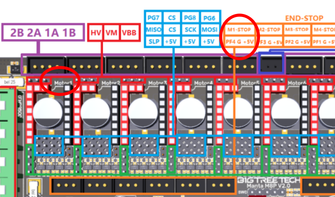
driver_SGTHRS: 255 # 255 is most sensitive value, 0 is least sensitiveThese changes on X are like that made on Y except for the diag_pin value. Why is ^PF4 specified here instead of cutting and pasting ^EBBCan: PB6 as we did on the Y axis??? Remember that our X axis limit switch is now the DIAG pin coming from TMC2209 stepper driver for the B Motor, which is "Motor 1" on the Manta Board. The EBB2209 toolboard is no longer involved in endstop detection. In fact, keeping the reference to ^EBBCan: PB6 in printer.cfg will cause this endstop to always show triggered, even when it isn't. But how do we know that ^PF4 is the right pin to specify??? We know from this picture from the BTT Manta Manual (opens in a new tab).
Additional Configuration
We will now add a new configuration file that contains variables and macros specific for homing X and Y using stallguard rather than physical switches.
- Go to this Github link (opens in a new tab) and download @kyleisah's
Sensorless-Homing.cfgto your PC (Discord reference) (opens in a new tab) - Review the variable definitions at the top of the file and make any changes you wish.
Trident users probably want to change variable_first_homed_axis: from 'X' to 'Y': if the printhead happens to be at the front of the printer and X is homed first, the printhead will move all the way to the right and bump into the front-right leadscrew.
- Upload the file
Sensorless-Homing.cfgto your printer whereprinter.cfgand all of the other configuration files are located - Edit your
printer.cfgfile to include this configuration file. If you put it near the top of the file, it will look as shown below.
[include mainsail.cfg]
[include stealthburner_leds.cfg]
[include Sensorless-Homing.cfg]
...
The printer.cfg files provided by MPX include a [safe_z_home] section. Per the Voron Guide (opens in a new tab), we want to comment this out in printer.cfg well. That section will look like this when you are done.
# [safe_z_home]
# home_xy_position:150,150
# speed:100
# z_hop:1
Be sure to save the printer.cfg file and restart the Klipper firmware when you are done.
Next Steps
At this point, your printer is set up for sensorless homing for when you get to running the initial startup checks (opens in a new tab) for your printer. In particular, the "Endstop Check" section (opens in a new tab) will verify that all Endstops are open (not triggered). Because of the work you have done to this point, the QUERY_ENDSTOPS command should show
x:open y:open z:openIf any of the endstops show as "triggered", you have made a mistake somewhere, either in the wiring or the software setup. Do not proceed further until you find the problem and fix it.
The "Endstop Check" section of that guide will in turn reference the Setting Up and Calibrating Sensorless XY Homing (opens in a new tab) documentation. You'll need to pick up that guide from the section on Finding the right StallGuard threshold (opens in a new tab). Note that the section on Homing Macros (opens in a new tab) from that page is already taken care of by the Sensorless-Homing.cfg file that we uploaded previously. Also, the steps in the Final Setup (opens in a new tab) section have been taken care of already as well: we commented out the [safe_z_home] section previously and our printer.cfg file already contains a [homing_override] section because it is needed for Tap.